JAVIER REYNA
Happy. Engineer. Designer.
The Vine Robot
You can find our most recent published paper here!
It covers our participation in RoboSoft 2018 and design for deployment of the robot
at underground tunnels in an archaeological site in Chavin, Peru last summer 2018.
RoboSoft 2018: IEEE-RAS International Conference on Soft Robotics


Images from RoboSoft 2018 Competition Recap (robosoft2018.org)


Redesigned the previous vine robot prototype and built a motorized version of the pre-formed vine robot for competing at RoboSoft 2018 (images from performance at the event shown above). In preparation for this, I built a replica of the 9-meter obstacle course, composed of:
a sand pit
a small gap sized smaller than the diameter of the end effector
three steps
unstable obstacles
Successfully completing the obstacle course at RoboSoft 2018, the vine robot won third place in the soft robot locomotion category.
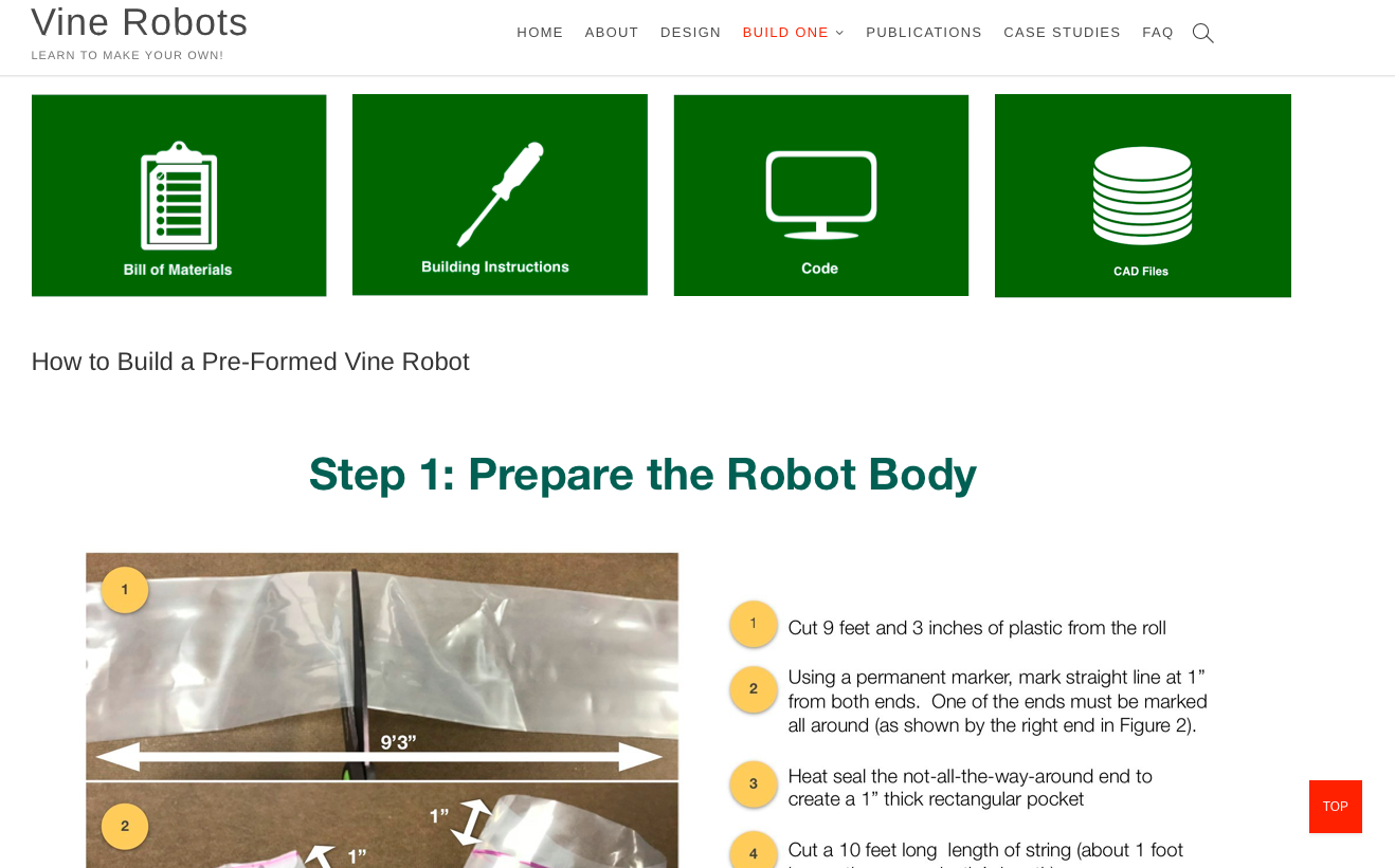
VineRobots.org: A Basic Introduction to What is a Vine Robot and How to Build One


Designed and built an educational website for the Vine Robot Research Project to:
showcase research and case studies relating the vine robot
provide an easily accessible platform for learning about vine robots
offer instruction on how to make a vine robot
This involved redesigning portions of the robot used during the RoboSoft 2018 conference to allow for ease of construction, decreased material cost, and modularity in order to make the technology more accessible to others. As part of CHARM Lab, I provide visitors with an introduction to the design of vine robots, how to build one, research publications for educational use, and case studies. The “How to Build One” sections contain a bill of materials (and where to obtain them), building instructions, CAD files for 3D printing, and Arduino code for operating the robot. This is meant to quick-start interested users, whether they only want to learn and build the 1-minute version or a fully operational pre-formed vine robot. Research publications and case studies give insight into current work and the details of research from the collaborating parties.
Stroke Patient Rehabilitation Exoskeleton

Overview

Parts were created via laser cutting, 3D printing, or purchased from Actobotics
The exoskeleton arm is a 2-degree-of-freedom (DOF) haptic device capable of planar movement with the following specs:
2-DOF Actuation
2 Motor-mounted Encoders
2 Joint Encoders
Pinion and Belt Drive
Low-Friction Joints
2 Maxon Motors
Background

Parts and assembly for rehabilitation device were designed in SolidWorks
Stroke is the main cause of adult disability and it occurs when blood flow to the brain is interrupted. The loss of blood flow to areas of the brain prevent those cells from getting the oxygen they need to function. These cells die, impairing the abilities that they control. A common ability that is lost is a patient’s sense of proprioception. Proprioception allows us to pinpoint the location of our limbs in space; it is the sense central to controlling movements. Although proprioception has been studied, there is no quantitative relationship between proprioceptive and motor impairments. If we could identify such a relationship, we would be able to devise a more individualized way to rehabilitate stroke survivors. This task requires the design, construction, and programming of an exoskeleton robot.
Proposed Experiment

1. Position Matching: Overlap cursor with a randomly generated red target within a set time.
2. Provide no visual feedback so that subjects rely only on proprioception

Exoskeleton Details
Adjustable height, linkage lengths, and arm supports
Ambidextrous design with a range of motion approximately 120 at the shoulder and 180 at the elbow
3D-printed, customizable and support/end-effector
Mobile base for portability and simple attachment to arm
Tensioning system for belts
Software:
Control:
Interfaced with the exoskeleton via Sensory826 PCIe board and Chai3d haptics libraries
Programmed in C++ using Microsoft Visual Studio
Positions mapped via forward/inverse kinematics
Graphics Interface:
Created using Chai3d visualization libraries
Mapped so that the physical and virtual position of the exoskeleton coincide
